Learn CAD by Designing a Robot in Fusion 360™
Computer Aided Design is incredibly powerful when you want to start a new project. You can visualize how pieces will fit together, how they will move, and even how they'll respond to forces. CAD projects are perfect pieces to put in your portfolio. A strong visual design speaks much more clearly to interviewers about your ability than words on your resume. Though CAD software has been historically expensive, it's now easier than ever to find an affordable package. For this project, I've selected to use Autodesk® Fusion 360™
Why Fusion 360?
Fusion 360 is a professional quality cloud-based 3D modeling software created by Autodesk. Unlike similar software, however, Fusion is completely free for students, educators, and hobbyists. This makes it the perfect platform to begin learning computer-aided design (CAD), and all skills gained in Fusion can easily translate into other CAD packages.
In this tutorial, I'll be showing you the basics of the software while we create a 3D model of a line following robot to complete a challenge. By completing this project, you'll have created plans for a functional robot. This is a comprehensive tutorial of the entire CAD process, and you'll utilize skills including:
- Hand Sketching
- Product Design
- 3D Modeling
- Rendering & Animation
If you're ready to begin learning, let's install Fusion, or get to the challenge!
If all you want to do is learn how to use Fusion 360, then you may wish to skip ahead to section 3.2.
Installation
If you've already got Fusion installed, then jump ahead to the next section!
Otherwise, download the current version here from Autodesk. and then launch the installer. Once the initial setup has completed, you will be prompted to either login or create an account:
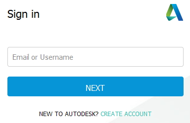
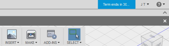
Create an Autodesk account if you do not already have one, and the program will begin. One of the particularly cool features of Fusion is that this account will store all of your files. This means that you can sign in using this account on any computer, and all of your models will be there. If this is your first time installing Fusion, you will see a warning prompting you that you have the trial version installed:

All that's left to do to activate your program completely is to click on the blue "Term ends in 30..." button in the top right corner of the program, and then select the appropriate option for your situation.
You're now good to go! Let's get to the challenge!
Design Challenge: Medieval Siege Engineer
A large, hostile castle looms in the distance. You, the time traveling engineer, have been tasked with designing a siege machine capable of reaching the castle walls. This machine must operate autonomously, and follow the existing path taken by your kingdom’s army. Reaching the castle will be quite a feat in itself, as your machine must be able to navigate the twists and turns of errant and distracted knights. Should your machine arrive in one piece, your next challenge is to breach the walls so that knights may follow. Should your machine have the capability of firing projectiles, it would make your king exceptionally proud to shoot down a tower as well.
Challenge Objectives
- Bronze - Design a robot capable of following an existing path full of twists and turns.
- Silver - Design a robot capable of following an existing path, and knocking down the door of the castle upon arrival.
- Gold - Design a robot capable of following an existing path, knocking down the front door, and shooting down a guard tower.
In the next section, you will find background information to help you get started. Your design may either be conceptual, or realistic. Should you choose to make it realistically, there will be future tutorials for simulating and building your design. I will be modeling it realistically.
Background
There are a variety of different ways to go about creating a line following robot. If you already have a favorite method, or aren't interested in designing for actual functionality, then jump ahead to project assets to get started.
If you are interested in actually building your design someday, then you'll find some basic background information on robotic line following in this section. For this challenge, I've decided to focus on one low-cost method utilizing photoresistors.
What are photoresistors?
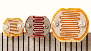
Photoresistors are similar to standard electrical resistors. However, their resistance changes based on the amount of light that hits them. In direct sunlight, a photoresistor provides close to zero resistance, and a circuit may function as if there were no resistor present at all. In darkness, however, a photoresistor provides an incredible amount of resistance, and can effectively block all current in a circuit.
How does this apply to line tracking?
By placing photoresistors facing straight down, we can effectively measure the amount of light being reflected by the surface below the robot. If a dark line exists on a light surface, then the current passing through a photoresistor will be less when the sensor is over a dark line. By placing multiple photoresistors on a robot, we can then determine where a dark line is positioned based on the voltage reading of each photoresistor.
Great, how do we do that?
To read such signals, one needs to use a microcontroller. For projects done at home, Arduinos are low-cost and readily available. By hooking up motors and photoresistors to an Arduino, and after a little bit of code, a robot can respond to changes in voltage across the photoresistors and automatically drive along a line while trying to keep it centered.

Project Assets
Here are several files that will help you begin designing your seige machine. If you plan to someday build your robot, I highly recommend creating an account over at GrabCAD. GrabCAD is a website that hosts user created 3D models for all kinds of things. It's a fantastic resource for when you need a quick model of something common like an Arduino or motor controller, and allows you to focus more on designing your project than recreating an existing product. Once you've gotten these assets downloaded, let's start designing.
Challenge Assets
Functional Robot Assets
These assets are to help you if you would like to use your robot model in my upcoming introduction to Arduino tutorial. Placing these realistically on your robot will allow you to actually build it. These models are from GrabCAD, and will save you a ton of time modeling. All credit goes to the authors of the parts I have chosen.
Concept Sketching
Now that you've gotten all of the project assets downloaded, let's get started designing our machine. Though I'm not a very good artist, I always try to develop a solid concept sketch before beginning design in Fusion. In this section, I will lay out my basic design, and try to show you how I go about drawing it. If you already have a design in mind, and feel confident about your sketching ability, then you may wish to skip this section and start in Fusion. If you feel more like me, and completely lost when it comes to drawing, then hopefully this well help you get started.
Minimally Viable Product
The challenge calls for a robot capable of following a previously established path on the road, and ideally able to fire projectiles. Rather than focusing initially on the ability to shoot and destroy things, I'm going to try to design a minimally viable robot simply capable of reaching the hostile castle. This is considered good practice in design, as you can always add fancy features after the initial design has been approved.
Design Requirements
Line Following
In order to achieve line tracking, I've decided to use photoresistors in combination with an Arduino. If you'd like a quick rundown on what exactly that means, then check out the background section. In order to get the robot to move, my design will require motors and wheels. In order to power everything, my robot will need some sort of power source. In summary, my design needs to include:
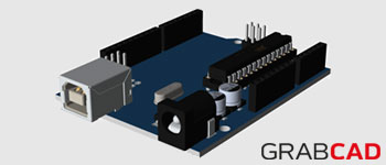
- Robot Brain - Arduino Uno
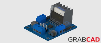
- Drive - Motors and Motor Controller
- Power Source - Batteries
- Path Sensors - Photoresistors
- Motion - Wheels
You have complete freedom over your design, and these are simply the required components of mine so that I can actually build it later. If you'd prefer to design a robot on treads using eyeballs to follow a line, then I would absolutely love to see it.
Blocking
Before I can magically spit out a detailed concept sketch, I start by "blocking" my design, or drawing rough shapes of where everything should go. This helps you to quickly make decisions on part placement, and saves you time from having to add detail. I began my blocked sketch with the Arduino, as it felt like the most important aspect of the robot. From there, I drew in motors and a motor controller, and then added smaller details such as the wheels and sensors. As you begin to design your own robot, consider how the placement of components may affect performance. For example, wheels too close to one another may make it difficult for the robot to turn. For my design, I researched a few line following robots on the internet, and got a basic idea of their layout. The sketch below animates in the order that I drew it, and the parts are as follows:
- Dark Blue - Arduino
- Red (M1 and M2) - Motors
- Turquoise (MC) - Motor Controller
- Green (W1 and W2) - Wheels
- Pink (S1, S2, S3) - Photoresistors
- Orange - Rear Slider
- Black - Body
Section Challenge: Detail Sketching
Most of the time, a simple blocked sketch is sufficient to start modeling. For those of you that would like to challenge yourself, this section will introduce an engineering method of creating more detailed drawings. If you'd rather spend time modeling than drawing, then hop on over to the next section and get started.
Orthographic Projection Method
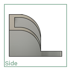
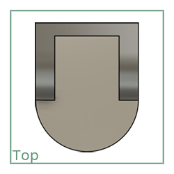
If you would like a better visualization of how your design will look, then it may help to produce a more detailed sketch. Drawing in 3D is always a challenge for nonartists (like me), so I use a method involving "orthographic projections." In a nutshell, this means that we imagine looking at the object from three different perspectives - front, side, and top. By combining each perspective view, we can then generate a 3D sketch of the object, or an "isometric view."
How the heck do you do that?
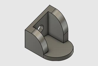
Vocab and concepts can only get you so far. In order to actually go about drawing each different projection, it can be helpful to imagine a glass cube surrounding your object. For example, say you've imagined the following (completely useless) 3D model in your head:
Now, imagine you've taken this object, and placed it inside of a clear glass cube:
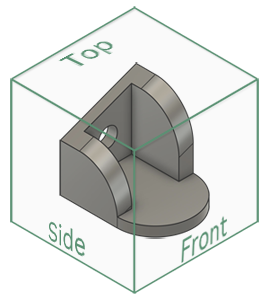
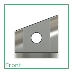
In order to create the "projections", imagine picking up the box, and rotating it so that you are looking straight into each labeled face. You would see the following views:
As you can see, the three images above no longer appear to be 3D and are instead simple shapes drawn in boxes. You could easily trace over each projected view. By referencing each of these three views on an empty cube, you can create a sketch of a 3D model.
My challenge to you is to blow my awful sketch out of the water by creating a detailed drawing of your concept. In order to complete this challenge, you must do the following:
- You already have a rough sketch of the top view. Now, generate the remaining views (side and front) to complete an orthogonal projection of your robot
- Draw a blank cube and construct a 3D sketch of your model by putting the views together
When you're done with your sketch, I would love to see it! Tag @mrJeffTeaches on Twitter, and I'll get back to you as soon as possible.
Project Setup
In this section, I'll give you a basic rundown of the interface and then help you load the project assets into Fusion 360™. You will learn most interface options while you actually make things, because I don't want you to waste your time reading boring content about the UI. If you haven't yet installed the program, then you probably should now.
The Interface
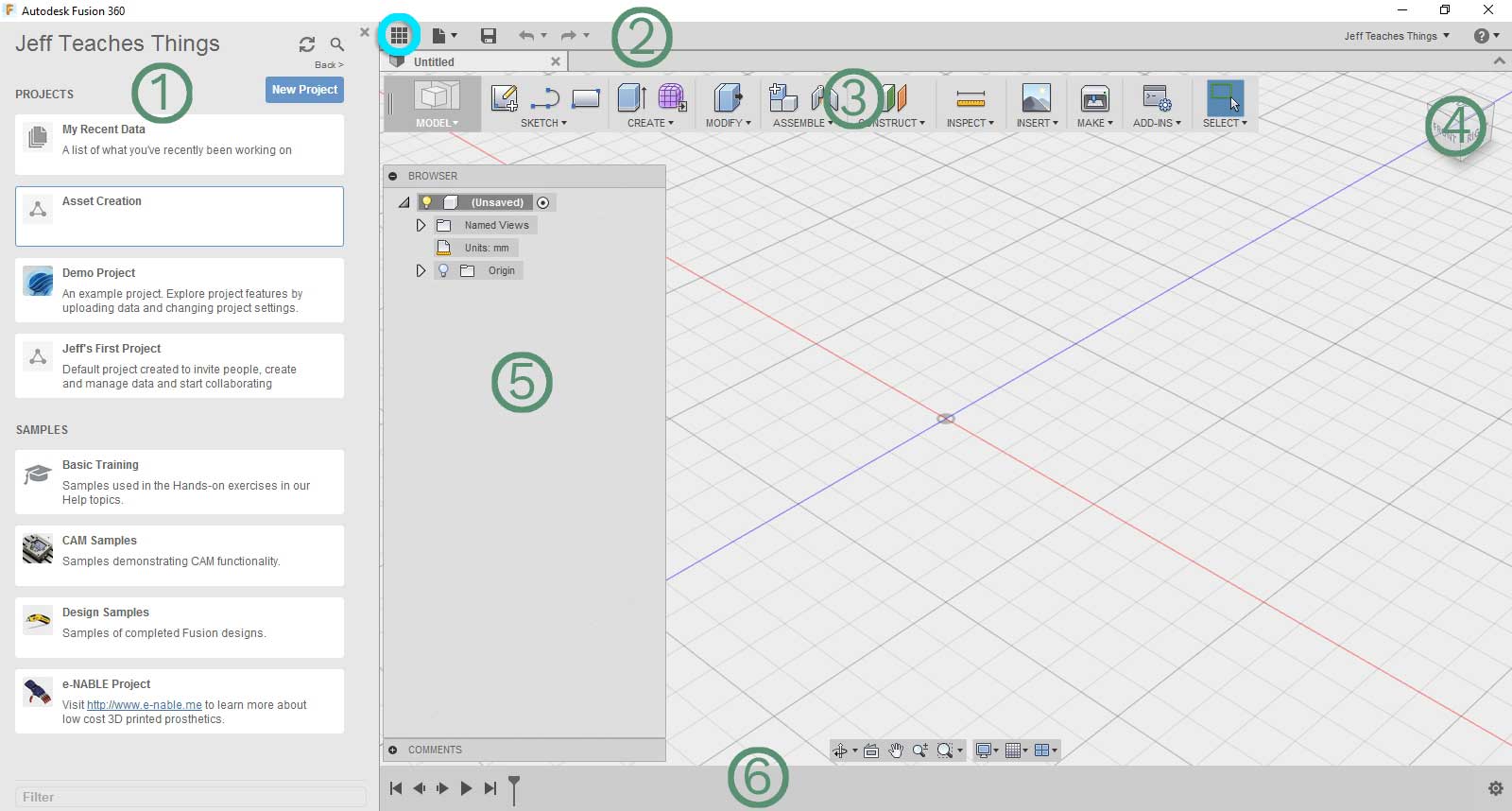
When you first open Fusion, you should be greeted with the following screen. The interface is broken down as follows:
- Data Panel - This is where you can create and manage "projects." Projects in Fusion are basically folders that help keep your related files together. You can also access built in tutorials from this panel. If this panel is not showing, then click the nine box icon that's circled in blue directly next to it to make it appear.
- Application Bar - Gives you basic file operation controls, like creating a new design or saving the current design.
- Toolbar - This is where you get all of the tools for modeling. Mouseover some of the options to get an idea of what you'll be working with.
- ViewCube - This nifty little box helps you rotate your camera into a desirable orientation. Clicking and dragging on the box makes your object rotate as if it were inside of the cube. Clicking directly on a side of the cube snaps your view to that side.
- Browser - This panel will show all of the current parts in your design. Many designs will be composed of multiple components, and the browser allows you to select and manipulate them individually.
- Timeline - This panel captures all of your actions in the order that you completed them. You can use a slider to step back in time and undo changes as well as modify previous actions.
Don't feel like you need to memorize everything right now - all of these will become very familiar to you as you continue to use the program.
Basic Controls
Fusion has an extensive hotkey system that will make your life significantly easier as you do more designing. Mousing over any icon on the toolbar will display information about what it does, and show you if it has a hotkey assigned.
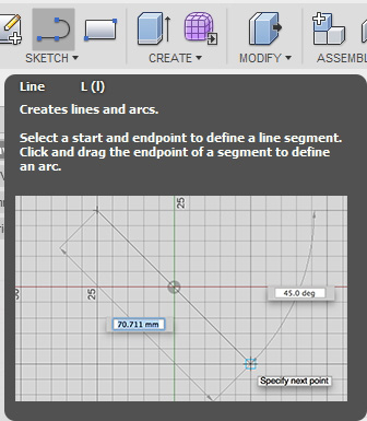
In this example, the name of the tool is Line, and the hotkey for the tool is L. This means that pressing L on the keyboard will activate the line tool. In addition to having hotkeys to select specific tools, there are hotkeys to navigate around the user interface as well. The main navigation keys are:
Scroll Wheel - Spin the scroll wheel to zoom the camera in and out.
Middle Click - Click and Drag with the middle mouse button to pan around the view.
Shift + Middle Click - Hold shift while clicking and dragging with the middle mouse button to rotate the view.
Loading Assets
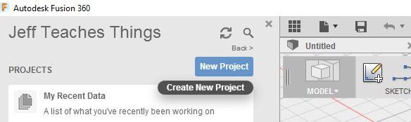
Now that you've got a basic understanding of the controls and layout of Fusion, it's time to create a project and load all of the downloaded assets. To create a new project, click on... "new project" on the data panel (panel one).
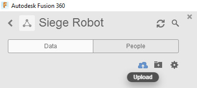
Name your project something cool like "Siege Robot", and then double click on it to enter the project space. The panel will be empty for now, as we have not yet loaded any files into it. To add the project assets to the project, click on the little cloud icon labeled "upload."
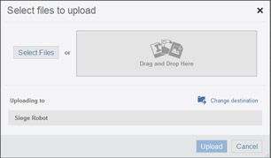
A select file window will pop up. Click on "Select Files" and then navigate to the downloaded assets. Once you've selected all of them, click on "Upload." Fusion requires you to upload pre-existing assets to the cloud in order to use them. This process may take a while, as Fusion does a significant amount of conversion before the file is ready to use.
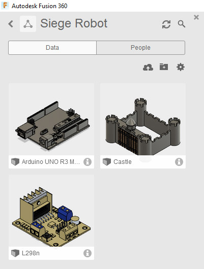
Don't be alarmed if the colors of the models are completely wrong. We are importing various formats into the software, and often the texture will not translate. Thankfully, textures are very easy to add, and I will be covering that in a later section. Your data panel should now be populated with all of the assets that you choose to upload.
Making Motors
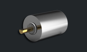
We've finally made it to the point where we can begin modeling! In this section, we'll be creating a basic DC motor that will power our siege robot. The motor we will be creating is simply a representation of what a typical motor may look like. The dimensions used are for visual purposes, and not measured off of an actual motor. If you happen to have a small DC motor, then you may wish to use its actual dimensions instead.
Extruding the Body
The typical workflow in CAD software involves creating a 2D sketch, and then transforming it into 3D using tools in the software. The first tool we will use is called "Extrude." This tool takes a closed 2D shape, and pulls it out of the page into 3D. To demonstrate, we'll be creating the body of the motor.
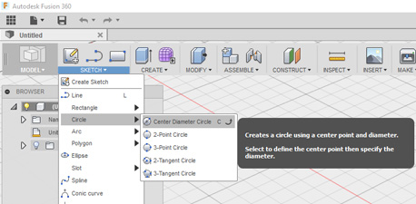
First, either press C on the keyboard or click on the "Sketch" dropdown, then mouseover "Circle" and select "Center Diameter Circle." This will select a tool that lets you draw 2D circles by specifying a center point and diameter.
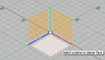
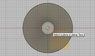
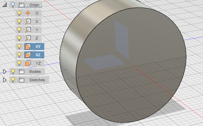
Because we're attempting to draw in 2D within a 3D space, we need to select a flat face to draw on. By default, Fusion provides three orange "origin" planes that correspond with the X, Y, and Z axes. In Fusion, the Z axis is blue, the X axis is red, and the Y axis is green. It doesn't really matter which plane you select to sketch on, as you can always rotate your object later. For now, we will select the plane highlighted in the following picture, the XZ plane.
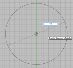
You are now in sketch mode, which is symbolized by the grid background on the screen. Click on the center icon to place the center of your circle at the origin. You can now either drag your mouse and click again to size the circle, or type in an exact value and press enter to size your circle. For the motor, let's try typing "1in" and pressing enter. You have now drawn a one inch diameter circle centered at the origin. Should you choose to use metric units instead, you can just as easily type something like "25mm". Fusion will automatically convert units for you.
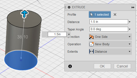
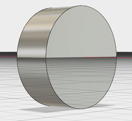
Click "Stop Sketch" on the bottom right to exit sketch mode and return to 3D. You will now see that your circle has been filled in with orange shading. This means that it's a closed profile, and able to be extruded. Press the E key on your keyboard, or click on the "Create" dropdown followed by "Extrude" to select the extrude tool. Now, click on the shaded part of your circle, and it should turn blue to signify that it has been chosen. Type in a distance, or click and drag the arrow upward to extrude the shape. On my motor, I used 1.5 inches.
You've now created a nice cylindrical body for your motor! Now that you've gone through the hassle of drawing and extruding a sketch, try playing around with other shapes. Use the sketch tools to draw various closed profiles, and then extrude to see them in 3D.
Creating the Shaft
Now that you've gone through all the trouble of creating a sketch and extruding it, let's do it all in one step to create the shaft. As I mentioned earlier, when you create a sketch in Fusion, you can select either a plane or a face to draw on. This allows us to build the shaft directly off of the motor body.
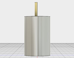
Click on the "Create" dropdown, and select "Cylinder." Now, click on the top face of the motor body. Click on the origin to set the center point, and then either drag the circle to an appropriate size or type "5mm" and press enter. Now, drag the arrow up until your shaft looks to be roughly the right size. Press enter or click okay to finish the shaft extrusion.
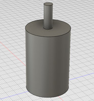
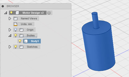
On the left side of your screen, click the dropdown arrow next to "Bodies." This will reveal a single entity called "Body1." If you click on it, you will see that the motor and shaft are combined into one single body. This doesn't really make sense, as in reality motors are composed of different moving parts, and aren't just single body pieces. Thankfully, Fusion makes it very easy to modify existing features.
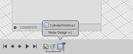
In order to modify previous actions, simply go down to the timeline on the bottom of your screen, and double click the action you wish to modify. An Edit Feature box will pop up, and you can modify parameters within it.
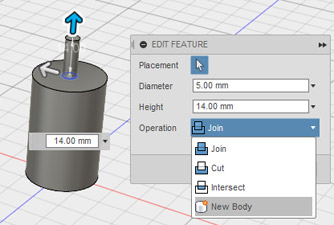
In order to seperate the shaft from the body of the motor, we will be creating the shaft as a new body. On the "Edit Feature" panel on the right side of your screen, there is an option called "Operation." Click the dropdown next to it, and select "New Body." Now, just complete the action and you will see two bodies listed on the browser bar - one for the shaft and one for the body. If you would like to name them, just double click on the entry in the browser bar, and type in a new name.
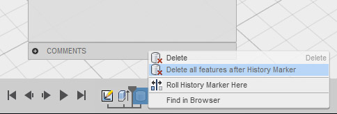
If you wish to undo a series of actions, you can also use the timeline to go back in time. Click and drag the history marker left and right to travel in time on your design. If you wish to undo all actions after a certain time, then place the marker in your desired spot, right click the next (grayed out) action, and choose "Delete All Features After History Marker."
Many DC motor shafts have a flattened side because it is easier to mount objects to a flat surface than a cylinder. In Fusion, extrude can be used to either create 3D parts, or cut away from existing 3D parts. To create the flattened side, we will be cutting away from the shaft. On the top right of your screen, click the "Top" side on the view cube. Now, click on "New Sketch" on the toolbar, and then click on the top face of the motor shaft.
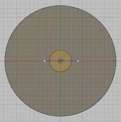
Now, either press "L" on the keyboard, or click on the Sketch dropdown followed by "Line." Draw a straight line across the motor shaft. It doesn't have to be perfectly symmetrical, it should just be straight and completely cross the motor shaft cylinder, like this:
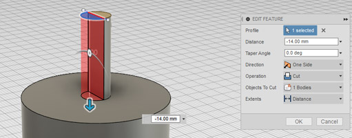
Finally, either press "E" on the keyboard, or click "Create" followed by "Extrude", and then click on the top half of the circle. Drag the arrow down toward the body, or type in a negative value to cut the shaft. You can also drag the arrow slightly, and then click on the top face of the motor to cut to that face.
Adding Textures
Plain gray models will only get you so far. Let's add some color to our motor.
Press "A" on the keyboard, or click on "Modify" followed by "Appearence" to open the Appearence Panel. At the top of this panel, you'll notice that you can choose between applying to entire bodies, or faces. For now, let's use the body selection. On your browser bar, select the body corresponding to the base of the motor.
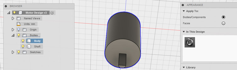
On the appearence panel, browse through the library to find a texture that you like. I chose "Stainless Steel - Polished" for my motor because I'm boring and realistic. Maybe your motor will be solid gold. You are on the king's payroll, after all. Once you find one you like, simply click and drag it onto the body of your motor. Do the same for the shaft, but with a different material so you can tell that they are different parts.
Your motor is now complete! If you'd like to add more detail to make it more realistic, check out the challenge below. Otherwise, let's make sensors!
Section Challenge: Adding More Detail
Your motor now looks solid, but certainly not extremely realistic. If you Google "DC Motor", you'll see some great examples of how real motors should look.
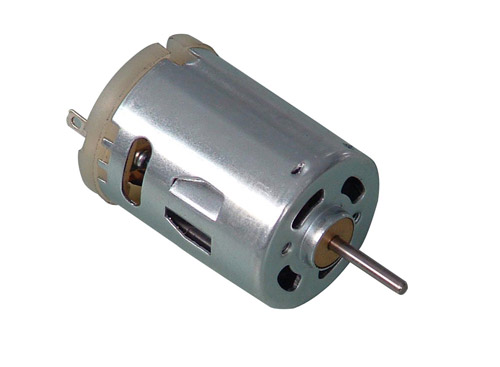
My challenge to you is to incorporate some additional realistic details into your 3D model. Specifically, focus on the details on the front face of the motor. There are four slotted holes, two circular holes, and a cylindrical base at the bottom of the shaft. Try adding these to your motor! You can create slots in Fusion by clicking "Sketch" followed by "Slot". Try your best, and let me know if you face any difficulties.
Making Sensors
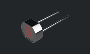
Now that we've got the basics of Fusion down, let's move on to our robot's eyes. Because I plan to actually build this robot, I will be modeling them after standard photoresistors, which you can read about in the background section of this tutorial. In this part of the tutorial, we'll use a few more advanced tools while still practicing the basics of extruding. Remember that the goal of this project is to create a siege robot, so if photoresistors are too boring for you, then please feel free to get creative!
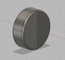
Creating the "Head"
The top part of the photoresistor, which I will call the "head", typically looks like a sort of rectangle with two rounded ends. In order to create this, I'm going to combine a circle and rectangle together in a sketch, and then extrude the result.
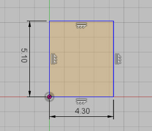
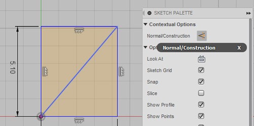
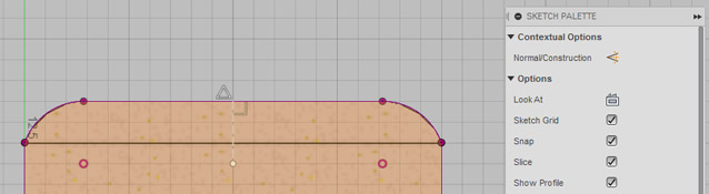
If you already have a part open, then click on the "File" dropdown at the top, followed by "New Design." If you're already on a new design, then create a new sketch on the plane of your choosing. Once the sketch begins, either select the Rectangle tool from the sketch dropdown, or press R on the keyboard. Click to start the corner of the rectangle on the origin, and then either drag it out to size, or type in dimensions. The photoresistor I'm referencing has a height of 5.1mm, and a width of 4.3mm.
Now, press L or select the Line tool, and draw a line from the bottom left corner of the rectangle to the top right corner. This is a quick trick to find the center of the rectangle. Click on the line, and then either press X, or click on "Normal/Construction" on the sketch palette. This creates what's known as a construction line, or a line that is only used for drawing purposes. Construction lines have no effect on the geometry of the part, but allow you to draw actual lines more precisely.
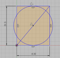
Press C on the keyboard, or select the center point circle tool, and then click on the center of your diagonal line. Drag the radius out, and snap it onto the center of one of the shorter length sides. It should look something like this:
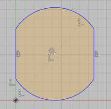
Go to Sketch, followed by "Trim" or press T on the keyboard. This tool allows you to cut off parts of lines based on where they intersect. Select the parts of the circle that go outside of the rectangle, as well as the corners of the rectangle. The final sketch should look like this:
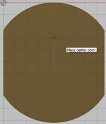
All that's left to do is to extrude the shape, which you learned in the last section. Go ahead and extrude it around 2mm. You should now have a basic 2mm thick head for your photoresistor.
Creating the Leads
The head of the photoresistor is completely useless unless we can actually wire something to it. We'll now add two leads to the bottom of the head to make it more functional.
Either using the hotkey (shift+middle mouse) or dragging the view cube, rotate your view to face the bottom of the head. I suppose the bottom is rather arbitrary, as it depends on which plane you initially started sketching on. Regardless, rotate your view to a side you want to designate as the bottom. Create a new sketch on the bottom face. Now, press C for the circle tool, and mouseover the center of your part. Move your mouse in a straight line from the origin to a curved side, and you'll see that the circle will automatically snap to be in line with the origin. Place a circle somewhere along this blue line, with a radius of .5mm.
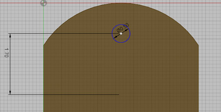
One of the strongest tools in CAD is the dimension tool. This allows you to precisely define where something should be placed, and makes it easy to modify later on. Either Click Sketch->Sketch Dimension, or press D on the keyboard to select it. Now click on the center of the circle you just drew, and then click on the point at the center of your part. Drag your mouse to the left, and you will see a line following with some numbers on it. Click once more to place it, and then double click it to edit it. Try changing it to a few different numbers, and watch how the circle slides up and down. Let's set it at 1.7mm for now.
The sensor has two leads that are symetrically spaced, so we'll reflect this existing one in order to introduce the mirror tool. The mirror tool allows you to take an existing sketch (or even 3D feature) and reflect it across an axis (or plane in 3D). We'll start by drawing the axis. Select the line tool, and then click on the center point of your part. Draw a line of any length directly to the side.
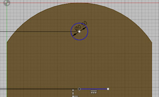
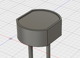
Now go to Sketch->Mirror, and click on your circle. On the mirror panel, click the box next to "Mirror Line", and then click on the horizontal line you just drew. Press "OK" and you will now see your circle reflected across the line. Modify the dimensions associated with your circle by double clicking them, and watch how the reflection changes as well. Neat-O (Sorry for saying that). Click on "Stop Sketch", then extrude and select both circles. Extrude them 10mm.
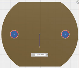
Hopefully you're not creeped out by the accidental face in that screenshot. I was delighted. I forgot to mention that the leads should be a new body. Thankfully, Fusion makes it easy to edit. Double click on the previous extrusion on the timeline, and change the operation to "New Body." Differentiating parts by bodies makes it nice and easy to apply materials later on.
You'll see that each lead became a seperate body in your browser. This is totally fine, and just happens because they're not connected to each other. Now that you've got the basic shape down, let's use a few more advanced tools to add detail.
Adding Detail
In this portion, we'll be adding a little bit of detail to the head of the photoresistor so that it looks more realistic. For most projects, you'll want to follow this same workflow where you start by creating a rough model of the overall shape, and then slowly add detail to make it look better.
Start by creating a new sketch on the top face of your photoresistor. Now, either select Sketch->Offset, or press the O key on your keyboard to select the "Offset" tool. This tool allows you to take an existing geometry, and offset it as a sketch. Click on the outline of your resistor's head. You'll see an outline pop up around it with a distance slider. Play around with it to get an idea of how it works, and then simply type in -.2mm.
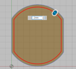
Great! Now extrude the innermost profile by -.1mm. Your head should now look like this:
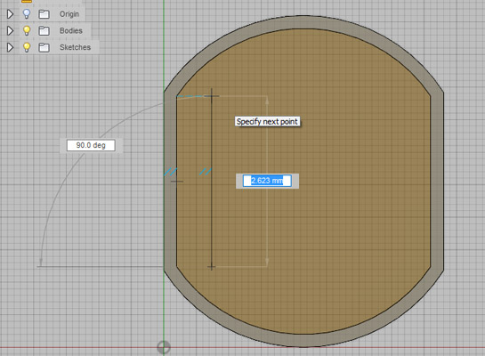
Now, we're going to add the wire onto this lower face. Create a new sketch on the face you just extruded. Select the line tool, then mouseover one of the newly created corners in order to snap your mouse to it. Without clicking, move your mouse slightly to the side, and then click to start your line. Drag up until it snaps to be inline with the next corner (you may also have to mouseover this edge without clicking). In the end, it should be something like this:
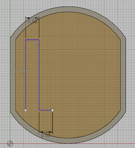
Pick one end of your line, and draw a line directly to the side of it a distance of around 0.5mm. From the end of this line, draw a new line parallel to your initial line. Finally, draw a line from this endpoint directly to the side of it a distance of .5mm. That was really hard to explain, so here's about how it should look:
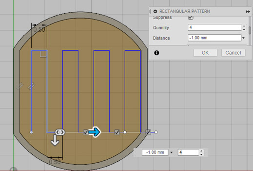
Part of the strength of CAD is repeatability - we can draw a shape like this once, and the computer can easily repeat it. To do this, we'll create a "Rectangular Pattern." Click the sketch dropdown, select "Rectangular Pattern" and then click on all the lines you just drew. If you look at the pattern panel, you'll see that you can select the distance type used. Extent allows you to create a certain amount of copies over a total distance, whereas spacing allows you to create a certain amount of copies with a set spacing in between. We'll use the spacing setting. Our horizontal lines were both .5mm long, so the spacing that we want will be 1mm. You may have to make this negative in order to force the pattern to go across the head rather than into space. I used a spacing of -1mm and a quantity of 4. If your pattern is going completely in the wrong dimension, then try scrolling down in the pattern panel and modifying the second set of parameters - rectangular patterns allow you to go in two directions, and it may not default in the correct one.
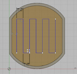
Once yours kind of looks like that picture, hit done. Next, individually select and delete (by hitting the delete key) each of the lines that go beyond the extruded face. It should end up looking like this:
Real wires, however, don't have sharp rectangular angles. To resolve this, select the Fillet tool from the sketch dropdown. Now, select a vertical line followed by a horizontal line, and you'll see a red curve appear, along with an option for radius. You can also just click on a corner point to have Fusion automatically choose.
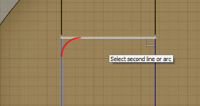
Play around with the radius size until you get a reasonable curve, and then repeat this for every corner of your line. My magic radius was .25mm.
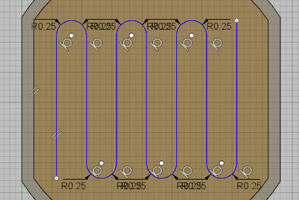
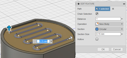
Now, let's turn this line into a wire. Click on the "Create" dropdown, and then select "Pipe." Now, click on every line in your curvy path. Change the operation to "New Body", and set the thickness around .15mm. Click create to 3D model your wire.
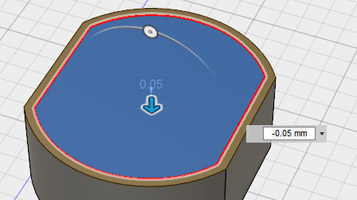
Finally, let's create the glass to protect the wire. Create a new sketch on the top face of the raised rim. Hit extrude, and select the inner profile. Set the operation to be New Body, and extrude it about .05mm down.
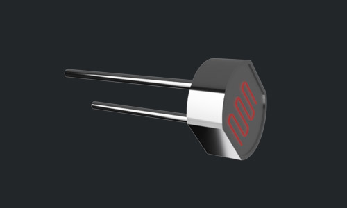
Finishing Up
You did it! Sure, it looks completely solid right now, but all you need to change that are a few materials. Select Modify->Appearence, or press A on the keyboard to select the appearence panel. Just like in the last section, select the "Bodies/Components" button, and then cycle through each of your bodies adding a material. For the glass face, I used "Glass - Light Color." This gives it a nice transparent look, and allows you to see your carefully modeled wire. Play around with some of the other materials until you get something you like, and then let's make some wheels!
Making Wheels
Congratulations on making it this far! Even if it may not feel like it, you've already learned a ton about CAD. At this point, I'm going to start backing off a bit on some of the tutorial steps and allow you to use what you know to create parts of models. I will still walk you through the workflow from start to finish, but you may have to figure out how to create a certain sized cylinder, for example. Remember, if you run into any issue at all, I'm here to help! Just throw @mrJeffTeaches a message, and I'll get back to you as soon as possible.
Here, I'll be walking you through creating some tires and wheels for our robot. The path doesn't appear to be too rocky, and I would like to reach the castle as quickly as possible, so my tires will be based on car tires.
Creating the Wheel
Remember how that introduction said something about me backing off a bit? Here's a perfect place to start! Create a solid cylinder that's 25mm in diameter, and 10mm in height. Be sure to place the center of your cylinder on the origin. Hint: you know various ways to do this (extrude/revolve/etc. ). I created mine on the YZ plane, if you would like to follow closely.
Creating the Tire
Well, we already have the most basic wheel possible, but it certainly won't work very well for driving our robot. Let's add a tire so that we can grip the road better.
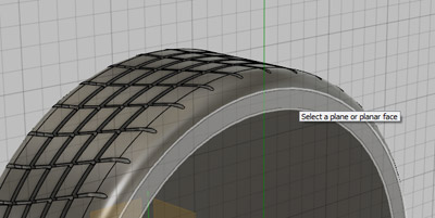
On your browser bar, expand the item labeled "Origin." Now, mouseover every item inside of it and watch how they highlight. We're looking for a workplane that is perpindicular to the flat face of your wheel. In my model, this would either be the XY or YZ planes:
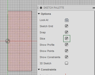
Create a new sketch on one of those planes by clicking on "New Sketch" and then the plane from the browser bar. The sketch should now be going directly through the middle of your wheel. Fusion has a nifty feature that allows us to hide all geometry between the sketch plane and our viewport. Check "Slice" on the sketch palette on the right side of your screen. You should now see something similar to this:
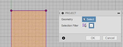
If you were to rotate your view a bit, you'd see everything on one side of the sketch plane has been hidden. This is a very useful feature, as it allows us to sketch within existing parts. Now, we would like to use this existing geometry in order to create our tire. To do this, press P on the keyboard, or go to Sketch, followed by "Project / Include" and finally "Project." Project takes the outline of your existing shape, and creates lines as if it were a 2D sketch. On the popup project panel, select "Bodies" and then click on the object in your sketch. You'll see it outline in a shade of pink, meaning that it's been projected onto your sketch, and you can now snap drawings to it.
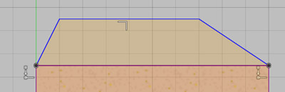
Make sure to snap your lines to the top corners of your wheel, and then draw a rough shape similar to this:
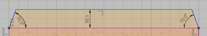
Now, use the dimension tool to accurately size your shape as follows. There are two 70 degree angles, and a 1mm height.
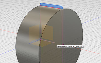
Click on Create -> Revolve, and then select your sketch profile. Click on Axis on the Revolve Panel, and then click on the axis going directly through the middle of your cylinder. Be sure to select "New Body" on the revolve panel, as this will be the tire that goes on your wheel. If you forget, just double click the revolve on your timeline and modify it to be a new body.
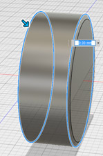
Go to Modify, followed by Fillet, or press F on the keyboard. Earlier, we used a tool with the same name to add curves to sharp edges on a 2D sketch. This is basically the same principle, but it works in 3D. Select the two circular edges of your tire, and set the radius to be 1.5mm.
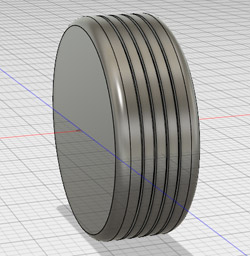
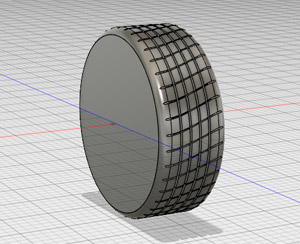
You now have a basic two body, smooth wheel! It's still not particularly effective, however, so let's add some detail.
Detailing the Tire
If we want to reach the castle without sliding all over the place, our tires will need some sort of grip. Here, I'll be modeling a basic tire tread.
Create a new sketch on one of the planes perpindicular to the flat face of your wheel. We've already used one of these planes in the previous section, so let's just pick the same one. It should again cut your wheel in half, basically.
Once again, check the slice button on the sketch palette to hide one side of the 3D model. Select Project from the sketch dropdown, or press P, and then select "Body" followed by the object. The edges of the object should turn into pink lines. Select the line tool, then mouseover the top line until a triangle becomes visible. The triangle means that you are at the midpoint of the line. Start a new line, and draw it straight down into the wheel any distance. After it has been drawn, select it and then turn it into a construction line from the sketch palette. At the end, you should have something like this:
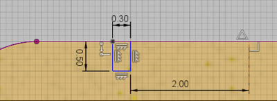
Using the rectangle tool, draw a rectangle .3mm wide by .5mm tall with one edge snapped to the edge of your tire. Dimension it so that it is 2mm away from the centerline.
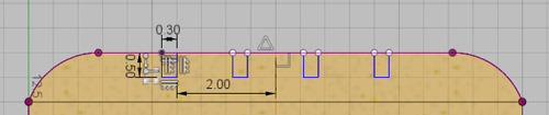
Now, use the rectangular pattern tool to create 4 copies over a total distance of 4.3mm. Previously, you used the rectangular pattern tool with spacing, but this time try it with "extent".
Revolve all four rectangles around the central axis of the wheel, and you should now have some nice grooves on your tire. Let's add a little more texture to make it better.
More Tire Details
Now, we're going to add some grooves in different directions to improve the tread of the tire. We're going to do this by creating a new body, and using it to cut into the existing one. Fusion excels in operations like this, and you'll be constantly combining and splitting bodies in order to create whatever you imagine.
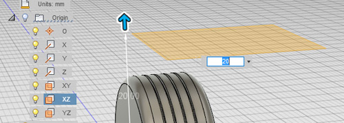
First, we need to create a "Work Plane" to sketch on. Usually we just use one of the built in planes, but often you'll have to create your own. Thankfully, it's very easy. Go to the construct panel, and select "Offset Plane". This feature allows us to take an existing plane, and create a new one by simply specifying a distance away from the initial location. With offset plane selected, pick one of the perpindicular planes from the browser menu. Click on it, and then drag it a distance of about 20 millimeters outside of the wheel. I chose the XZ plane, and pulled it straight up 20mm.
Actions like this are extremely useful whenever you need to manipulate a curved surface, as sketches require a flat surface. Create a new sketch on this workplane, and project the geometry of the wheel body. Draw a horizontal line across the middle of your wheel.
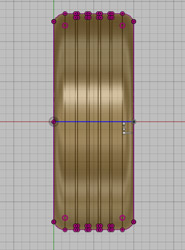
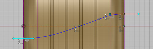
Set the centerline as a construction line. Now, select the spline tool from the sketch dropdown. If you've never used one before, splines are very weird. You essentially place points, and a curvy line follows that connects every point. Using the spline tool, draw something like this, with part of the line below the centerline, part of it above, and one point placed on the midpoint. Once you have drawn every point, click on the little circle check mark to finish the spline. You'll be greeted with lovely green handles all over your drawing. I placed 5 points total.
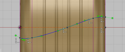
Those green handles are called "Bezier Handles". They control the influence of every point on the curve of the line. Try clicking on one and dragging it around, and watch how the spline changes. Try to drag your handles around to get a nice smooth curve going. If you're like me at all, then it will probably take several tries to make it look right.
Now, use the pipe tool on your smooth line. Set the section size to be .25mm.
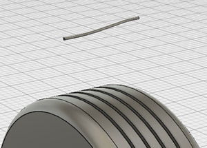
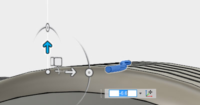
"Great, Jeff. I have a random pipe above my tire." Let's put it to better use. Select move from the modify dropdown, or press M on the keyboard. This will grab the move tool, which allows you to accurately move bodies around. Go to your browser bar, and click on the pipe body. You'll see moveable arrows appear near the model. Drag the pipe straight down until it comes in contact with the tire. I dragged mine down 6.6mm.
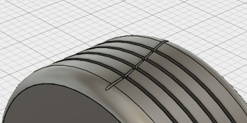
Select combine from the modify dropdown, and then select the tire as the "Target Body." Select the pipe as the "Tool Body." Change the operation to "Cut", and then press OK. Voila, the pipe cut a nice tread into our tire!
One tread won't do much good, so select "Circular Pattern" from the Create dropdown. Much like how rectangular pattern copies a shape along a line, circular pattern copies a shape around a circle. Fusion lets you do this in 3D with features as well. For objects, go down to your timeline and select "Combine1". Choose the axis through the center of your tire as the axis of revolution. The number is really at your discretion - I used 40. The more you use, the harder your computer will have to work to create them. Now that's starting to look like a tire!
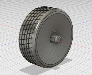
Wheel Details
You now have a pretty solid looking wheel. If you're sick of adding detail, then just pop on a few materials and head on over to the next section. If you want to go above and beyond, then we'll be adding some nice detail to the hub of our wheel in this section.
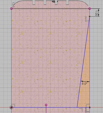
Start by creating a new sketch on one of the central planes of the wheel. Slice your sketch, and project the geometry so you have stuff to snap to. Draw a nice fat triangle from the center of the wheel to just below the tread. Dimension it as follows, with the top point being 1mm below the tread, and the triangle having an 8 degree angle. Make sure that the triangle ends on the midline of your wheel (you may have to draw a construction line to snap it properly).
Great! Now, revolve the triangle around the center axis of the wheel as a cut. This won't make a huge difference yet, but it still looks kind of nifty. Create a new sketch on the flat portion of the hubcap, as shown below:
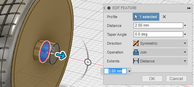
Draw a 4mm diameter circle, centered on the origin. Hit extrude, then select "Symmetric" on the Operation dropdown. Type in 2mm for the distance, and make sure it's set to "Join."
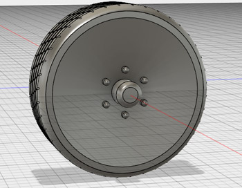
Fillet the outermost edge of this extruded cylinder to your liking. I chose .8mm to add a slight curve. Create another sketch on the flat face of your hubcap, just like before. Draw a 3mm long line from the center of the wheel straight up. This line will act as a spacer for a bolt circle. Draw a small 1mm circle centered on the end of the line. Extrude the circle so that it goes inside of the wheel, and be sure to select "Join". You should now have something funky, like this:
Fillet the top of the bolt as you desire (I used .5mm). Using our good friend, the circular pattern tool, create 6 more bolts around the central axis. I would use the "Pattern Features" option, and select the extrusion and fillet from the timeline.
Almost there! All that's left is to add a mounting plate. Select "Offset Plane", and then click on the flat surface of your wheel that we've been using. Move it towards the wheel a distance of 1mm. You should be able to easily distinguish where the plane comes in and out of the wheel.
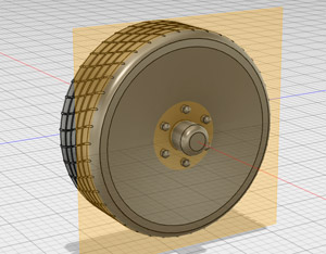
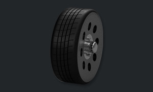
Create a sketch on this plane, and draw a circle larger than the circular area of the plane coming out of the wheel in the center. In the picture above, you can clearly see this circle around the center. Extrude your circle back into the wheel, and select join. Add materials to your heart's content.
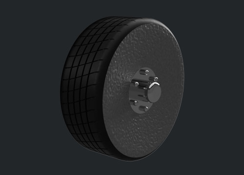
Congratulations! You've got a wheel with some really neat detail. My detail, however, is certainly not very exciting. If you're looking for a bit of a challenge, then try adding a bit of spice to your design. Add some spikes to the hubcap, some gnarly offroad treads, or anything that tickles your fancy. The point is to experiment and have fun with it - you'll master the program much quicker if you deviate a little bit from my guidance. Let's go start putting everything together.